
Logic Gates - OR, AND, NOT, NAND and NOR
Logic Gates - OR, AND, NOT, NAND and NOR: Overview
This topic covers concepts, such as, Types of Signals, Analogue Signals, And Gate using Diode & Uses of Logic Gates etc.
Important Questions on Logic Gates - OR, AND, NOT, NAND and NOR
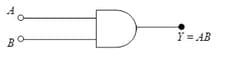
It is representing:
The logic gate given below represents a
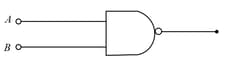
The same input signal is applied to both the (input) terminals of a given logic gate.
If the output is the(i) same as the (common) input signal
(ii) inverted with respect to the (common) input signal,
Identify the logic gate/s involved in each case.
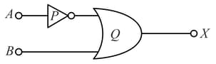
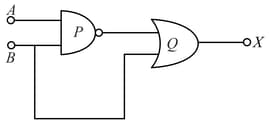
Write down the output at for the inputs and
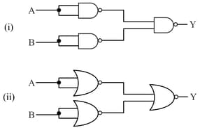
Identify the logic gates marked and in the given logic circuit.
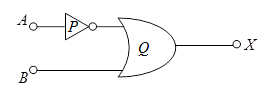
Identify the logic gates marked P and Q in the given logic circuit.
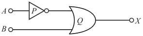
(i) Identify the logic gates marked P and Q in the given logic circuit.
The inputs A and B are inverted by using two NOT gates and their outputs are fed to the NOR gate as shown below.
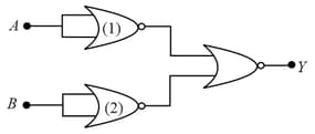
Analyse the action of the gates (1) and (2) and identify the logic gate of the complete circuit so obtained.
While realising a NOT gate, for low input, n-p-n transistor is in cut-off mode.
In the formation of a two-input OR gate using two diodes, negative terminal of one diode is connected to the positive terminal of another diode.
What are logic gates made of?
What is a logic function?
What is a logic element?
How logic gates are used in real life?
What are the uses of logic gates?
Where is NOR gate used?
What is the expression of XNOR gate?
How do you write a NOR gate?
Is NOR the same as and?
Is NOR gate and XOR gate same?


